Warning Before working on a chassis or working near power supplies, unplug the power cord on AC units; disconnect the power at the circuit breaker on DC units. (To see translated versions of this warning, refer to the appendix "Translated Safety Warnings.")
Installing WAN Modules
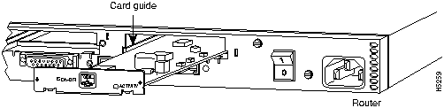
You can install WAN modules in the router without removing the chassis cover. Each router chassis can accommodate up to three WAN modules---two synchronous serial and one ISDN. The choice of synchronous serial WAN modules is as follows:
- 2-wire switched 56-kbps DSU/CSU
- 4-wire 56/64-kbps DSU/CSU
- Fractional T1/T1 DSU/CSU
- Five-in-one synchronous serial
The choice of ISDN WAN modules is as follows:
- ISDN BRI
- ISDN with integrated NT1 device
The ISDN WAN modules are designed so that you cannot insert them into the synchronous serial WAN slots. A blank slot cover is installed over unused slots.
Take the following steps to install a WAN module:
Step 1 Turn OFF power to the router.
Caution Unlike some other Cisco routers, the WAN modules are not hot-swappable (that is, you cannot remove or install them when power to the router is ON). Be sure to turn OFF power to the router before installing or removing WAN modules. Failure to do so may damage or halt the router.
Step 2 Remove the WAN module from the ESD-protective shipping material.
Step 3 Slide the WAN module into the appropriate slot along the card guides until it is completely seated in the connector inside the router (see Figure A-1).
Step 4 Tighten the two captive screws on the module to secure it to the chassis.
Caution Although there are three slots available for the WAN modules, the slot on the far right (labeled BRI 0) is reserved for an ISDN WAN module only. Install all other modules in the slots labeled SERIAL 0 and SERIAL 1. The ISDN WAN modules are designed so that you cannot insert them into the synchronous serial slots.
Figure A-1 : Installing a WAN Module
Step 5 If your router is configured with less than three WAN modules, make sure a blank slot cover is installed over each open slot to ensure proper airflow inside the chassis.
Opening the Chassis
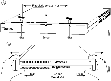
This section describes the procedure for opening the chassis by removing the chassis cover.
Warning Do not touch the power supply when the power cord is connected. For systems with a power switch, line voltages are present within the power supply even when the power switch is OFF and the power cord is connected. For systems without a power switch, line voltages are present within the power supply when the power cord is connected. (To see translated versions of this warning, refer to the appendix "Translated Safety Warnings.")
Tools Required
You will need the following tools to open the chassis:
- Medium-size flat-blade screwdriver (1/4 inch [0.625 cm])
- Size M 3.5 (metric) hex-head nut driver (optional)
Removing the Chassis Cover
You must open the router chassis to gain access to its interior components: the system card, system-code single in-line memory modules (SIMMs), and DRAM SIMMs. When opening the chassis, refer to Parts A and B in Figure A-2.
Warning Before opening the chassis, disconnect the telephone-network cables to avoid contact with telephone-network voltages. (To see translated versions of this warning, refer to the appendix "Translated Safety Warnings.")
Take the following steps to remove the chassis cover:
Step 1 Turn OFF the power, but to channel electrostatic discharge (ESD) voltages to ground, do not unplug the power cable.
Step 2 Remove all interface cables from the rear panel of the router.
Step 3 Turn the unit upside down so that the top of the chassis is resting on a flat surface, and the front of the chassis is toward you. (See Figure A-2, Part A.)
Figure A-2 : Chassis Cover Removal
Step 4 Remove the single screw located on the bottom of the chassis (on the side closest to you). Note that the chassis is comprised of two sections: top and bottom.
Step 5 If required, insert a medium-size flat-blade screwdriver into the slots shown in Figure A-2, Part A, and gently rotate the blade so that the top and bottom sections separate slightly.
Step 6 Holding the chassis with both hands, position it as shown in Figure A-2, Part B.
Step 7 Pull the top section away from the bottom section. (See Figure A-2, Part B.) The fit is very snug, so it may be necessary to pry the chassis sections apart at one end and then the other until they separate.
Step 8 When the top cover is off, set it aside. Figure A-3 shows the layout of the system card, which is attached to the bottom section of the chassis.
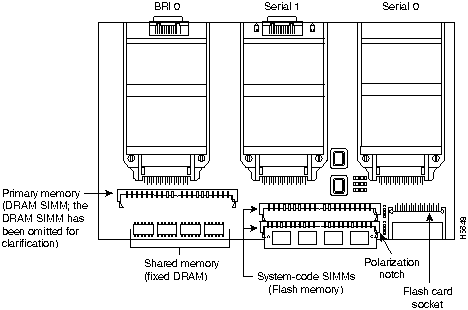
Figure A-3 : System Card Layout---Cisco 2524
Upgrading the Boot Flash Memory
Take the following steps to upgrade the boot Flash memory:
Step 1 Turn OFF power, but to channel ESD voltages to ground, do not unplug the power cord.
Step 2 Attach an ESD-preventive wrist strap.
Step 3 Open the cover following the instructions in the section "Opening the Chassis" earlier in this appendix.
Step 4 Insert the Flash memory card into the Personal Computer Memory Card International Association (PCMCIA) slot.
Step 5 Turn ON power to the router. The system copies the boot image on the Flash memory card to the boot Flash memory on the system card:
Cisco Systems
Diagnostic Monitor
Testing boot state
Exiting boot state
Testing Main Memory from 0h to C000h. data equals address
Testing Main Memory from 0h to C000h. checkerboard
Testing Main Memory from 0h to C000h. inverse checkerboard
Clearing bss
Enabling interrupts
Exiting init
Boot flash size = 0x200000
etext = 0x1006860
addr = 0x1006861
beginning of header file addr = 0x1006874
got the flash file header number 1
Program flash location 0x81ed000
Boot flash frier is successful.
Please turn off the system and remove the Flash Credit Card.
Step 6 Remove the Flash memory card and turn ON power to the router.
Upgrading the DRAM SIMM
This section describes how to upgrade the DRAM SIMM on the system card. You might need to upgrade the DRAM SIMM for the following reasons:
- You upgrade the Cisco IOS feature set or release.
- Your router maintains large routing tables or other memory-intensive features, such as spoofing or protocol translations.
There are two types of DRAM memory in the Cisco 2524 and Cisco 2525 routers: fixed DRAM soldered on the system card and a removable DRAM SIMM (see Figure A-3). The DRAM SIMMs are available in 4, 8, or 16 MB. Depending on the Cisco IOS feature set originally ordered with your router, it may or may not include fixed DRAM. If the Cisco IOS feature set requires a DRAM configuration other than 4, 8, or 16 MB, your router will have a combination of fixed DRAM and a DRAM SIMM. For example, if the Cisco IOS feature set originally ordered with your router requires 6-MB DRAM, your router will include 2-MB fixed DRAM and a 4-MB DRAM SIMM for a total of 6-MB DRAM (because a 6-MB DRAM SIMM is not available).
The system allocates the total memory installed on the fixed DRAM or the DRAM SIMM as primary and shared memory. Primary memory is used to store the operating configuration, routing tables, caches, queues, and packets. Shared memory is used to store incoming and outgoing packets.
Table A-1 describes the relationship between the physical configuration of DRAM (that is, fixed DRAM and which size DRAM SIMM are needed to obtain from 2- to 18-MB of total DRAM) and how the system allocates the DRAM as shared and primary DRAM.
Table A-1 : DRAM Physical Configuration and System Allocation
2
|
2
|
--
|
1
|
1
|
4
|
--
|
4
|
2
|
2
|
6
|
2
|
4
|
2
|
4
|
8
|
--
|
8
|
2
|
6
|
10
|
2
|
8
|
2
|
8
|
16
|
--
|
16
|
2
|
14
|
18
|
2
|
16
|
2
|
16
|
To see how much memory is currently installed in the router, enter the show version command. Near the middle of the resulting output, a message similar to the following displays:
Cisco XXXX(68030) processor (revision X) with 4092K/2048K bytes of memory.
This line shows how much memory is installed (in this example, 4092K/2048K). The first number represents primary memory and the second number represents shared memory.
Tools and Equipment Required
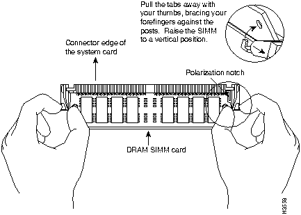
You will need the following tools to remove and replace the DRAM SIMM on the router:
- Medium-size flat-blade screwdriver (1/4 inch [0.625 cm])
- ESD-preventive wrist strap
- The DRAM SIMM required for your planned upgrade
DRAM SIMM Installation
Take the following steps to install the DRAM SIMMs:
Step 1 Turn OFF power to the router, but to channel ESD voltages to ground, do not unplug the power cord.
Step 2 Attach an ESD-preventive wrist strap.
Step 3 Open the cover following the instructions in the section "Opening the Chassis" earlier in this appendix.
Step 4 Orient the chassis as shown in Figure A-3, with the primary-memory DRAM SIMM socket toward you.
Step 5 Remove the existing DRAM SIMM by pulling outward on the connectors to unlatch them, as shown in Figure A-4. Be careful not to break the holders on the SIMM connector.
Caution To prevent damage, do not press on the center of the SIMMs. Handle each SIMM carefully.
Figure A-4 : Removing and Replacing the DRAM SIMM
Step 6 Using the system card orientation shown in Figure A-4, position the new SIMM so that the polarization notch is located at the right end of the SIMM socket.
Step 7 Insert the new DRAM SIMM by sliding the end with the metal fingers into the SIMM connector socket at approximately a 45-degree angle to the system card. Gently rock the SIMM back into place until the latch on either side snaps into place. Do not use excessive force because the connector may break.
Step 8 Replace the router cover. Follow the instructions in the section "Closing the Chassis" later in this appendix.
Step 9 Connect the router to a console terminal.
Step 10 Turn ON power to the router. If error messages relating to memory are displayed, remove the DRAM SIMM and reinstall it, taking care to firmly seat the SIMM in its socket.
Replacing System-Code SIMMs
The system code (software) is stored in Flash memory SIMMs. The 80-pin Flash memory SIMMs must be purchased from Cisco Systems. Contact a customer service representative for more information.
Note The system code for both the Cisco 2524 and Cisco 2525 can be contained on either one or two 80-pin Flash memory SIMMs. If only one 80-pin SIMM socket is populated, it must be the SIMM socket indicated in Figure A-3 (labeled CODE0).
Tools and Equipment Required
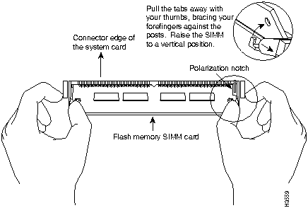
You will need the following tools to remove and replace the system-code SIMMs on the router:
- Medium-size flat-blade screwdriver (1/4 inch [0.625 cm])
- ESD-preventive wrist strap
- The appropriate system-code SIMM(s) for your router
System-Code SIMM Replacement
Take the following steps to upgrade the system-code Flash memory SIMMs:
Step 1 Turn OFF the power, but to channel ESD voltages to ground, do not unplug the power cord.
Step 2 Attach an ESD-preventive wrist strap.
Step 3 Open the chassis cover following the procedure in the section "Opening the Chassis" earlier in this appendix.
Step 4 Orient the chassis as shown in Figure A-3, with the system-code SIMMs toward you.
Step 5 Locate the system-code SIMMs on the system card. The SIMM sockets are labeled CODE0 and CODE1. (See Figure A-3.)
Step 6 Remove the existing system-code SIMM by pulling outward on the connector holders to unlatch them. The connector holds the SIMM tightly, so be careful not to break the holders on the SIMM connector. (See Figure A-5.)
Caution To prevent damage, do not press on the center of the SIMMs. Handle each SIMM carefully.
Step 7 Repeat these steps for all the system-code SIMMs to be replaced.
Figure A-5 : Removing and Replacing the System-Code SIMM
Step 8 Using the system card orientation shown in Figure A-5, position the new SIMM so that the polarization notch is located at the right end of the SIMM socket.
Caution To prevent damage, note that some Flash memory SIMMs have the components mounted on the rear side; therefore, when inserting the SIMM, always use the polarization notch as a reference and not the position of the components on the SIMM.
Step 9 Insert the new SIMM by sliding the end with the metal fingers into the appropriate SIMM connector socket (labeled CODE0 or CODE1 in Figure A-3) at approximately a 45-degree angle to the system card. Gently rock the SIMM back into place until the latch on either side snaps into place. Do not use excessive force because the connector may break.
Step 10 Replace the router cover following the procedure in the next section, "Closing the Chassis."
Step 11 Connect the router to a console terminal.
Step 12 Turn ON the power to the chassis. If any error messages relating to memory display, remove the system-code SIMM and reinstall it, taking care to firmly seat the SIMM in the socket.
Closing the Chassis
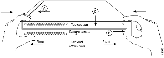
This section describes the procedure for closing the chassis.
Tools Required
You will need the following tools to replace the cover:
- Medium-size flat-blade screwdriver (1/4 inch [0.625 cm])
- Size M 3.5 hex-head nut driver (optional)
Replacing the Cover
After you perform the maintenance for your system, perform the following steps to replace the cover:
Step 1 Position the two chassis sections, as shown in Figure A-6.
Step 2 Referring to Figure A-6, press the two chassis sections together and ensure the following:
- The top section fits into the rear of the bottom section. (See A in Figure A-6.)
- The bottom section fits into the front of the top section. (See B in Figure A-6.)
- Each side of the top and bottom sections fits together. (See C in Figure A-6.)
Caution To fit the two sections together, it may be necessary to work them together at one end and then the other, working back and forth; however, use care to prevent bending the chassis edges.
Figure A-6 : Replacing the Chassis Cover
Step 3 When the two sections fit together snugly, turn the chassis so that the bottom is facing up, with the front panel toward you.
Step 4 Replace the cover screw. (See Figure A-2.) Tighten the screw to no more than 8 or 9 inch/pounds of torque.
Step 5 Reinstall the chassis on the wall, rack, desktop, or table.
Step 6 Replace all cables.
Recovering Lost Passwords
This section explains how to recover the following types of passwords:
- An enable secret password (a very secure, encrypted password). The enable secret password is available on routers running Cisco IOS Release 10.3(2) or later.
- An enable password (a less secure, nonencrypted password). The enable password is used when the enable secret password does not exist.
- A console password. The console password is used to prevent unauthorized users from attempting to change the router configuration. When a console password is set, you must provide a password to log in to the console and access user EXEC mode.
The key to recovering a lost enable password is to set the configuration register so that the contents of NVRAM are ignored (0x142), which allows you to see your password. The enable secret password is encrypted and cannot be recovered; it must be replaced. The enable and console passwords might be encrypted or clear text.
Take the following steps to recover a lost password:
Step 1 Plan for some system downtime. The password recovery procedure requires a system reload.
Step 2 Connect a terminal to the console port on the rear panel of the router. Make sure the terminal is configured to operate at 9600 baud, 8 data bits, no parity, and 2 stop bits.
Step 3 Enter the show version command to display the existing configuration register value. The configuration register value is on the last line of the display. Note whether the configuration register is set to enable or disable Break.
- The factory-default configuration register value is 0x2102. Notice that the third digit from the left in 0x2102 is 1, which disables Break. If the third digit is not 1, Break is enabled.
Step 4 If the configuration register is set to disable Break, power cycle the router. (Turn the router OFF, wait five seconds, and then turn the router ON again.) If the configuration register is set to enable Break, press the Break key or send a Break signal to the router and then proceed to Step 6.
Note If your keyboard does not have a Break key, refer to your terminal or terminal emulation software documentation for information about how to send a Break signal to the router.
Step 5 Within 60 seconds of turning ON the router, press the Break key or send a Break signal. The ROM monitor prompt (>) appears.
Step 6 Enter the o/r command to reset the configuration register to boot from the boot ROMs and ignore NVRAM:
>
o/r 0x142
Step 7 Enter the initialize command to initialize the router:
>
initialize
- The router power cycles and the configuration register is set to 0x142. The router boots the system image in Flash memory and the System Configuration Dialog appears:
--- System Configuration Dialog ---
Step 8 Enter no in response to the System Configuration Dialog prompts until the following message appears:
Press RETURN to get started!
Step 9 Press Return.
Step 10 Enter privileged EXEC mode and then enter the show startup-config command to display the passwords in the configuration file:
Router>
enable
Router#
show startup-config
Step 11 Scan the configuration file displayed for the passwords (the enable and enable secret passwords are usually near the beginning of the file and the console password is near the end of the file). An example display follows:
enable secret 5 $1$ORPP$s9syZt4uKn3SnpuLDrhuei
enable password sand
.
.
line con 0
password seashells
- Proceed to Step 12 to replace an enable secret, console, or enable password. If there is no enable secret password, note the enable and console passwords, if they are not encrypted, and proceed to Step 15.
Caution Do not take the next three steps unless you have determined that you must change or replace the enable, enable secret, or console passwords. Failure to follow the steps as shown might cause you to erase your router configuration.
Step 12 Enter the configure memory command to modify or replace passwords in NVRAM:
Router#
configure memory
Step 13 Enter the configure terminal command to enter configuration mode:
Router#
configure terminal
Step 14 Change only the passwords that are necessary for your configuration. The following example shows how to change all three types of passwords. The first two lines show how to change the enable secret and enable passwords. The last two lines show how to change the console password.
Router(config)#
enable secret pail
Router(config)#
enable password shovel
Router(config)#
line con 0
Router(config-line)#
password con1
- For maximum security, be sure the enable secret and enable passwords are different.
- You can remove individual passwords by using the no form of these commands. For example, enter the no enable secret command to remove the enable secret password.
Step 15 Configure all interfaces to be administratively up. In the following example, the Ethernet 0 port is configured to be administratively up:
Router(config-line)#
interface ethernet 0
Router(config-if)#
no shutdown
- Enter the equivalent commands for all interfaces that were originally configured.
Step 16 Set the configuration register to the original value you noted in Step 3 or the factory-default value (0x2102). The following example shows how to set the configuration register to the factory-default value:
Router(config-if)#
config-register 0x2102
Router(config)#
Step 17 Press Ctrl-Z to exit configuration mode.
Caution Do not take the next three steps unless you have changed or replaced a password or you might erase your router configuration. If there is no enable secret password (or if you skipped Step 12 through Step 14), proceed to Step 21 and log in.
Step 18 Enter the copy running-config startup-config command to save the new configuration to NVRAM. This command copies the changes you just made to the running configuration to the startup configuration. The following message appears:
Router#
copy running-config startup-config
Building configuration...
[OK]
Router#
Step 19 Reboot the router:
Router#
reload
Proceed with reload? [confirm]
Step 20 Press Return to confirm. When the router reboots it will use the new configuration register value you set in Step 16.
Step 21 Log in to the router with the new or recovered passwords.
Virtual Configuration Register Settings
The router has a 16-bit virtual configuration register, which is written into NVRAM. You might want to change the virtual configuration register settings for the following reasons:
- Set and display the configuration register value
- Force the system into the ROM monitor or boot ROM
- Select a boot source and default boot filename
- Enable or disable the Break function
- Control broadcast addresses
- Set the console terminal baud rate
- Recover a lost password (ignore the configuration file in NVRAM)
- Enable Trivial File Transfer Protocol (TFTP) server boot
Table A-2 lists the meaning of each of the virtual configuration memory bits, and defines the boot field names.
Caution To avoid confusion and possibly halting the router, remember that valid configuration register settings might be combinations of settings and not just the individual settings listed in Table A-2. For example, the factory default value of 0x2102 is a combination of settings.
Table A-2 : Virtual Configuration Register Bit Meanings
00--03
|
0x0000--0x000F
|
Boot field
|
06
|
0x0040
|
Causes system software to ignore the contents of NVRAM (startup-config)
|
07
|
0x0080
|
OEM bit is enabled
|
08
|
0x0100
|
Break is disabled
|
10
|
0x0400
|
IP broadcast with all zeros
|
11--12
|
0x0800--0x1000
|
Console line speed
|
13
|
0x2000
|
Load the boot ROM software if a Flash boot fails five times
|
14
|
0x4000
|
IP broadcasts do not have network numbers
|
15
|
0x8000
|
Enable diagnostic messages and ignore the contents of NVRAM
|
1 The factory default value for the configuration register is 0x2102. This value is a combination of the following: bit 13 = 0x2000, bit 8 = 0x0100, and bits 00 through 03 = 0x0002.
Changing Configuration Register Settings
Take the following steps to change the configuration register while running the Cisco IOS software:
Step 1 Enter the enable command and your password to enter privileged mode:
Router>
enable
password:
router#
Step 2 Enter the configure terminal command at the privileged-level system prompt (Router#):
Router#
configure terminal
Step 3 To set the contents of the configuration register, enter the configuration command config-register value, where value is a hexadecimal number preceded by 0x (see Table A-2 and Table A-3):
config-register 0x
value
- (The virtual configuration register is stored in NVRAM.)
Table A-3 : Explanation of Boot Field (Configuration Register Bits 00 to 03)
0x0
|
Stops the boot process in the ROM monitor.
|
0x1
|
Stops the boot process in the boot ROM monitor.
|
0x3--0xF
|
Specifies a default filename for booting over the network from a TFTP server.
Enables boot system commands that override the default filename for booting over the network from a TFTP server.
|
0x2
|
Full boot process, which loads the Cisco IOS image in Flash memory.
|
Step 4 Press Ctrl-Z to exit configuration mode. The new settings will be saved to memory; however, the new settings do not take effect until the system software is reloaded by rebooting the router.
Step 5 To display the configuration register value currently in effect and the value that will be used at the next reload, enter the show version EXEC command. The value displays on the last line of the screen display:
Configuration register is 0x142 (will be 0x102 at next reload)
Step 6 Reboot the router. The new value takes effect. Configuration register changes take effect only when the router restarts, which occurs when you switch the power OFF and ON or when you enter the reload command.
Virtual Configuration Register Bit Meanings
The lowest four bits of the virtual configuration register (bits 3, 2, 1, and 0) form the boot field. (See Table A-3.) The boot field specifies a number in binary form. If you set the boot field value to 0, you must boot the operating system manually by entering the b command at the bootstrap prompt, as follows:
> b [tftp] flash filename
The b command options are as follows:
- b---Boots the default system software from ROM
- b flash---Boots the first file in Flash memory
- b filename [host]---Boots from the network using a TFTP server
- b flash [filename]---Boots the file filename from Flash memory
For more information about the command b [tftp] flash filename, refer to the Router Products Configuration Guide publication for Cisco IOS Release 11.0 and earlier releases. Refer to the Configuration Fundamentals Configuration Guide publication for Cisco IOS Release 11.1 and later releases.
If you set the boot field value to a value of 0x2 through 0xF, and a valid system boot command is stored in the configuration file, the router boots the system software as directed by that value. If you set the boot field to any other bit pattern, the router uses the resulting number to form a default boot filename for booting from the network using a TFTP server. (See Table A-4.)
Table A-4 : Default Boot Filenames
bootstrap mode
|
0
|
0
|
0
|
0
|
ROM software
|
0
|
0
|
0
|
1
|
cisco2-igs
|
0
|
0
|
1
|
0
|
cisco3-igs
|
0
|
0
|
1
|
1
|
cisco4-igs
|
0
|
1
|
0
|
0
|
cisco5-igs
|
0
|
1
|
0
|
1
|
cisco6-igs
|
0
|
1
|
1
|
0
|
cisco7-igs
|
0
|
1
|
1
|
1
|
cisco10-igs
|
1
|
0
|
0
|
0
|
cisco11-igs
|
1
|
0
|
0
|
1
|
cisco12-igs
|
1
|
0
|
1
|
0
|
cisco13-igs
|
1
|
0
|
1
|
1
|
cisco14-igs
|
1
|
1
|
0
|
0
|
cisco15-igs
|
1
|
1
|
0
|
1
|
cisco16-igs
|
1
|
1
|
1
|
0
|
cisco17-igs
|
1
|
1
|
1
|
1
|
In the following example, the virtual configuration register is set to boot the router from Flash memory and to ignore Break at the next reboot of the router:
router> enable
password: enablepassword
router# conf term
Enter configuration commands, one per line.
Edit with DELETE, CTRL/W, and CTRL/U; end with CTRL/Z
config-register 0x102
boot system flash [filename]
^Z
router#
The router creates a default boot filename as part of the automatic configuration processes. The boot filename consists of cisco, plug the octal equivalent of the boot field number, a hyphen, and the processor type.
Note A boot system configuration command in the router configuration in NVRAM overrides the default boot filename.
Bit 8 controls the console Break key. Setting bit 8 (the factory default) causes the processor to ignore the console Break key. Clearing bit 8 causes the processor to interpret the Break key as a command to force the system into the bootstrap monitor, thereby halting normal operation. A break can be sent in the first 60 seconds while the system reboots, regardless of the configuration settings.
Bit 10 controls the host portion of the IP broadcast address. Setting bit 10 causes the processor to use all zeros; clearing bit 10 (the factory default) causes the processor to use all ones. Bit 10 interacts with bit 14, which controls the network and subnet portions of the broadcast address. (See Table A-5.)
Table A-5 : Configuration Register Settings for Broadcast Address Destination
Off
|
Off
|
<ones> <ones>
|
Off
|
On
|
<zeros> <zeros>
|
On
|
On
|
<net> <zeros>
|
On
|
Off
|
<net> <ones>
|
Bits 11 and 12 in the configuration register determine the baud rate of the console terminal.
Table A-6 shows the bit settings for the four available baud rates. (The factory-set default baud rate is 9600.)
Table A-6 : System Console Terminal Baud Rate Settings
9600
|
0
|
0
|
4800
|
0
|
1
|
1200
|
1
|
0
|
2400
|
1
|
1
|
Bit 13 determines the server response to a bootload failure. Setting bit 13 causes the server to load operating software from ROM after five unsuccessful attempts to load a boot file from the network. Clearing bit 13 causes the server to continue attempting to load a boot file from the network indefinitely. By factory default, bit 13 is set to 1.
Enabling Booting from Flash Memory
To disable Break and enable the boot system flash command, enter the config-register command with the value shown in the following example:
router> enable
Password: enablepassword
router# config term
Enter configuration commands, one per line.
Edit with DELETE, CTRL/W, and CTRL/U; end with CTRL/Z
config-reg 0x2102
^Z
router#
Copying a Cisco IOS Image to Flash Memory
You may need to copy a new Cisco IOS image to Flash memory whenever a new image or maintenance release becomes available. To copy a new image into Flash memory (write to Flash), you must first reboot from ROM and then copy the new image into Flash memory. You cannot copy a new image into Flash memory while the system is running from Flash memory. Use the copy tftp flash command for the copy procedure.
Take the following steps to copy a new image to Flash memory:
Step 1 Enter the show flash command to make sure there is enough space available before copying a file to Flash memory. Compare the size of the file you want to copy to the amount of available Flash memory displayed.
Step 2 Make a backup copy of the current image.
Step 3 Enter enable mode and then enter the copy tftp flash command to copy the new image into Flash memory:
Router>
enable
Password:
enablepassword
Router#
copy tftp flash
- The following messages display:
**** NOTICE ****
Flash load helper v1.0
This process will accept the copy options and then terminate
the current system image to use the ROM based image for the copy.
Routing functionality will not be available during that time.
If you are logged in via telnet, this connection will terminate.
Users with console access can see the results of the copy operation.
---- ******** ----
Proceed? [confirm]
Step 4 Press Return to confirm. If there is an image already in Flash memory, the router displays the name and size of the file. Then the router prompts you for the IP address or name of the remote host:
Address or name of remote host [hostname]?
- The remote host can be a server or another router with a valid Flash system software image.
Step 5 Enter the IP address or name of the remote host. The router then prompts you for the name of the source file:
Source file name?
Step 6 Enter the name of the source file. The following prompt displays:
Destination file name [filename]?
Step 7 Press Return to accept the default filename or enter a different filename. Messages similar to the following display:
Accessing file 'master/igs-j-l.110-4.2' on hostname...
Loading master/igs-j-l.110-4.2 from 172.16.72.1 (via Ethernet0): ! [OK]
Erase flash device before writing? [confirm]
yes
Step 8 Enter yes to erase the contents of Flash memory. The following message displays:
Flash contains files. Are you sure you want to erase? [confirm]
yes
Step 9 Enter yes to confirm that you want to erase the contents of Flash memory. Messages similar to the following display:
%SYS-5-RELOAD: Reload requested
%FLH: master/igs-j-l.110-4.2 from 172.16.72.1 to flash ...
System flash directory:
File Length Name/status
1 3459776 username/igs-i-l
[3459840 bytes used, 4928768 available, 8388608 total]Configuration mapped ip address 172.16.72.1 to hostname
Accessing file 'master/igs-j-l.110-4.2' on hostname...
Loading master/igs-j-l.110-4.2 from 172.16.72.1 (via Ethernet0): ! [OK]
Erasing device... eeeeeeeeeeeeeeeeeeeeeeeeeeeeeeee ...erased
Loading master/igs-j-l.110-4.2 from 172.16.72.1 (via Ethernet0): !!!!!!!!!!!!!!!!!!!!!!!!!!!!!!!!!!!!!!!!!!!!!!!!!!!!!!!!!!!!!!!!!!!!!!!!!!!!!!!!!!!!!!!!!!!!!!!!!!!!!!!!!!!!!!!!!!!!!!!!!!!!!!!!!!!!!!!!!!!!!!!!!!!!!!!!!!!!!!!!!!!!!!!!!!!!!!!!!!!!!!!!!!!!!!!!!!!!!!!!!!!!!!!!!!!!!!!!!!!!!!!!!!!!!!!!!!!!!!!!!!!!!!!!!!!!!!!!!!!!!!!!!!!!!!!!!!!!!!!!!!!!!!!!!!!!!!!!!!!!!!!!!!!!!!!!!!!!!!!!!!!!!!!!!!!!!!!!!!!!!!!!!!!!!!!!!!!!!!!!!!!!!!!!!!!!!!!!!!!!!!!!!!!!!!!!!!!!!!!!!!!!!!!!!!!!!!!!!!!!!!!!!!!!!!!!!!!!!!!!!!!!!!!!!!!!!!!!!!!!!!!!!!!!!!!!!!!!!!!!!!!!!!!!!!!!!!!!!!!!!!!!!!!!!!!!!!!!!!!!!!!!!!!!!!!!!!!!!!!!!!!!!!!!!!!!!!!!!!!!!!!!!!!!!!!!!!!!!!!!
[OK - 6196336/8388608 bytes]
Verifying checksum... OK (0x2997)
Flash copy took 0:03:38 [hh:mm:ss]
%FLH: Re-booting system after download
- The system reboots using the new image in Flash memory.
Note For more information about the copy tftp flash command and other related commands, refer to the publication Router Products Configuration Guide for Cisco IOS Release 11.0 and earlier releases. For Cisco IOS Release 11.1 and later releases, refer to the publication Configuration Fundamentals Configuration Guide.
Copyright 1988-1996 © Cisco Systems Inc.