|
|

In the 1970s, a set of protocols was needed to provide users with wide-area network (WAN) connectivity across public data networks (PDNs). PDNs such as TELENET and TYMNET had achieved remarkable success, but it was felt that protocol standardization would increase subscription to PDNs by providing improved equipment compatibility and lower cost. The result of the ensuing development effort was a group of protocols, the most popular of which is X.25.
X.25 was developed by the common carriers (telephone companies, essentially) rather than any single commercial enterprise. The specification is therefore designed to work well regardless of a user's system type or manufacturer. Users contract with the common carriers to use their packet-switched networks (PSNs) and are charged based on PSN use. Services offered (and charges levied) are regulated by the Federal Communications Commission (FCC).
One of X.25's unique attributes is its international nature. X.25 and related protocols are administered by an agency of the United Nations called the International Telecommunications Union (ITU). The International Telecommunication Union Telecommunication Standardization Sector (ITU-T) (formerly CCITT) is the ITU committee responsible for voice and data communications. ITU-T members include the FCC, the European Postal Telephone and Telegraph organizations, the common carriers, and many computer and data communications companies. As a result, X.25 is truly a global standard.
X.25 defines a telephone network for data communications. To begin communication, one computer calls another to request a communication session. The called computer can accept or refuse the connection. If the call is accepted, the two systems can begin full-duplex information transfer. Either side can terminate the connection at any time.
The X.25 specification defines a point-to-point interaction between data terminal equipment (DTE) and data circuit-terminating equipment (DCE). DTEs (terminals and hosts in the user's facilities) connect to DCEs (modems, packet switches, and other ports into the PDN, generally located in the carrier's facilities), which connect to packet switching exchanges (PSEs, or simply switches) and other DCEs inside a PSN and, ultimately, to another DTE. The relationship between the entities in an X.25 network is shown in Figure 12-1.
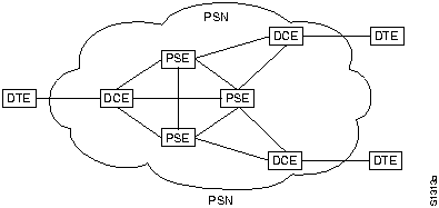
A DTE can be a terminal that does not implement the complete X.25 functionality. A DTE is connected to a DCE through a translation device called a packet assembler/disassembler (PAD). The operation of the terminal-to-PAD interface, the services offered by the PAD, and the interaction between the PAD and the host are defined by ITU-T Recommendations X.28, X.3, and X.29, respectively.
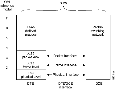
The X.25 specification maps to Layers 1 through 3 of the OSI reference model. Layer 3 X.25 describes packet formats and packet exchange procedures between peer Layer 3 entities. Layer 2 X.25 is implemented by Link Access Procedure, Balanced (LAPB). LAPB defines packet framing for the DTE/DCE link. Layer 1 X.25 defines the electrical and mechanical procedures for activating and deactivating the physical medium connecting the DTE and the DCE. This relationship is shown in Figure 12-2. Note that Layers 2 and 3 are also referred to as the ISO standards ISO 7776 (LAPB) and ISO 8208 (X.25 packet layer).
Figure 12-2 : X.25 and the OSI Reference Model
End-to-end communication between DTEs is accomplished through a bidirectional association called a virtual circuit. Virtual circuits permit communication between distinct network elements through any number of intermediate nodes without the dedication of portions of the physical medium that characterizes physical circuits. Virtual circuits can either be permanent or switched (temporary). Permanent virtual circuits are commonly called PVCs; switched virtual circuits are commonly called SVCs. PVCs are typically used for the most-often-used data transfers, while SVCs are used for sporadic data transfers. Layer 3 X.25 is concerned with end-to-end communication involving both PVCs and SVCs.
Once a virtual circuit is established, the DTE sends a packet to the other end of the connection by sending it to the DCE using the proper virtual circuit. The DCE looks at the virtual circuit number to determine how to route the packet through the X.25 network. The Layer 3 X.25 protocol multiplexes between all the DTEs served by the DCE on the destination side of the network and the packet is delivered to the destination DTE.
An X.25 frame is composed of a series of fields, as shown in Figure 12-3. Layer 3 X.25 fields make up an X.25 packet and include a header and user data. Layer 2 X.25 (LAPB) fields include frame-level control and addressing fields, the embedded Layer 3 packet, and a frame check sequence (FCS).
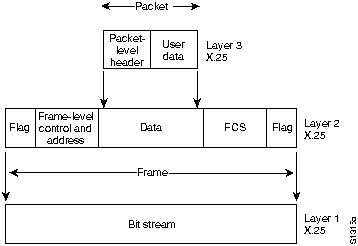
The Layer 3 X.25 header is made up of a general format identifier (GFI), a logical channel identifier (LCI), and a packet type identifier (PTI). The GFI is a 4-bit field that indicates the general format of the packet header. The LCI is a 12-bit field that identifies the virtual circuit. The LCI is locally significant at the DTE/DCE interface. In other words, the PDN connects two logical channels, each with an independent LCI, on two DTE/DCE interfaces to establish a virtual circuit. The PTI field identifies one of X.25's 17 packet types.
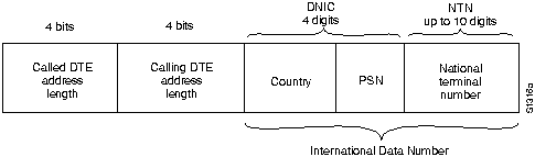
Addressing fields in call setup packets provide source and destination DTE addresses. These are used to establish the virtual circuits that constitute X.25 communication. ITU-T Recommendation X.121 specifies the source and destination address formats. X.121 addresses (also referred to as International Data Numbers, or IDNs) vary in length and can be up to 14 decimal digits long. Byte four in the call setup packet specifies the source DTE and destination DTE address lengths. The first four digits of an IDN are called the data network identification code (DNIC). The DNIC is divided into two parts, the first (three digits) specifying the country and the last specifying the PSN itself. The remaining digits are called the national terminal number (NTN), and are used to identify the specific DTE on the PSN. The X.121 address format is shown in Figure 12-4.
Figure 12-4 : X.121 Address Format
The addressing fields that make up the X.121 address are only necessary when an SVC is used, and then only during call setup. Once the call is established, the PSN uses the LCI field of the data packet header to specify the particular virtual circuit to the remote DTE.
Layer 3 X.25 uses three virtual circuit operational procedures:
Execution of these procedures depends on the virtual circuit type being used. For a PVC, Layer 3 X.25 is always in data transfer mode because the circuit has been permanently established. If an SVC is used, all three procedures are used.
Packets are used to transfer data. Layer 3 X.25 segments and reassembles user messages if they are too long for the maximum packet size of the circuit. Each data packet is given a sequence number, so error and flow control can occur across the DTE/DCE interface.
Layer 2 X.25 is implemented by LAPB. LAPB allows both sides (the DTE and the DCE) to initiate communication with the other. During information transfer, LAPB checks that the frames arrive at the receiver in the correct sequence and error-free.
As with similar link-layer protocols, LAPB uses three frame format types:
The LAPB frame is shown in Figure 12-5.
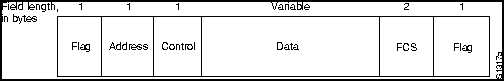
The fields of a LAPB frame are as follows:
Layer 1 X.25 uses the X.21 bis physical-layer protocol, which is roughly equivalent to
EIA/TIA232C (formerly RS-232-C). X.21 bis was derived from ITU-T Recommendations V.24 and V.28, which identify the interchange circuits and electrical characteristics (respectively) of a DTE to DCE interface. X.21 bis supports point-to-point connections, speeds of up to 19.2 kbps, and synchronous, full-duplex transmission over four-wire media. The maximum distance between DTE and DCE is 15 meters.
|
|
Copyright 1988-1996 © Cisco Systems Inc.