|
|
In the early 1980s, as Apple Computer, Inc. was preparing to introduce the Macintosh computer, Apple engineers knew that networks would become a critical need. They wanted to ensure that a Macintosh-based network was a seamless extension of the revolutionary Macintosh user interface. With these two goals in mind, Apple decided to build a network interface into every Macintosh and to integrate that interface into the desktop environment. Apple's new network architecture was called AppleTalk.
Although AppleTalk is a proprietary network, Apple has published AppleTalk specifications in an attempt to encourage third-party development. Today, many companies are successfully marketing AppleTalk-based products, including Novell, Inc. and Microsoft Corporation.
The original implementation of AppleTalk, which was designed for local workgroups, is now commonly referred to as AppleTalk Phase 1. With the installation of over 1.5 million Macintosh computers in the first 5 years of the product's life, however, Apple found that some large corporations were exceeding the built-in limits of AppleTalk Phase 1, so they enhanced the protocol. The enhanced protocol, known as AppleTalk Phase 2, improved the routing capabilities of AppleTalk and allowed AppleTalk to run successfully in larger networks.
AppleTalk was designed as a client-server distributed network system. In other words, users share network resources (such as files and printers) with other users. Computers supplying these network resources are called servers; computers using a server's network resources are called clients. Interaction with servers is essentially transparent to the user because the computer itself determines the location of the requested material and accesses it without further information from the user. In addition to their ease of use, distributed systems also enjoy an economic advantage over peer-to-peer systems because important materials can be located in a few, rather than many, locations.
In Figure 16-1, AppleTalk protocols are shown adjacent to the OSI layers to which they map.
Figure 16-1 : AppleTalk and the OSI Reference Model
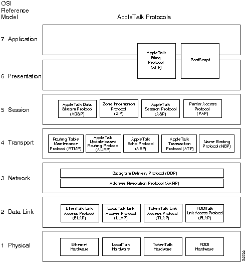
Apple designed AppleTalk to be link-layer independent. In other words, it can theoretically run on top of any link-layer implementation. Apple supports a variety of link-layer implementations, including Ethernet, Token Ring, Fiber Distributed Data Interface (FDDI), and LocalTalk. Apple refers to AppleTalk over Ethernet as EtherTalk, to AppleTalk over Token Ring as TokenTalk, and to AppleTalk over FDDI as FDDITalk. The link-layer protocols that support AppleTalk over these media are EtherTalk Link Access Protocol (ELAP), LocalTalk Link Access Protocol (LLAP), TokenTalk Link Access Protocol (TLAP), and FDDITalk Link Access Protocol (FLAP). For more information about the technical characteristics of Ethernet, Token Ring, and FDDI, see Chapter 5, "Ethernet/IEEE 802.3," Chapter 6, "Token Ring/IEEE 802.5," and Chapter 7, "Fiber Distributed Data Interface," respectively.
LocalTalk is Apple's proprietary media-access system. It is based on contention access, bus topology, and baseband signaling, and runs on shielded twisted-pair media at 230.4 kbps. The physical interface is EIA/TIA-422 (formerly RS-422), a balanced electrical interface supported by EIA/TIA-449 (formerly RS-449). LocalTalk segments can span up to 300 meters and support a maximum of 32 nodes.
This section describes AppleTalk network-layer concepts and protocols. It includes discussion of protocol address assignment, network entities, and AppleTalk protocols that provide OSI reference model Layer 3 functionality.
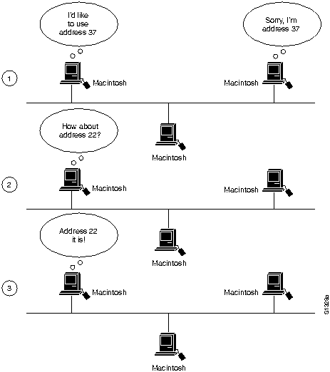
To ensure minimal network administrator overhead, AppleTalk node addresses are assigned dynamically. When a Macintosh running AppleTalk starts up, it chooses a protocol (network-layer) address and checks to see whether that address is currently in use. If not, the new node has successfully assigned itself an address. If the address is currently in use, the node with the conflicting address sends a message indicating a problem, and the new node chooses another address and repeats the process. Figure 16-2 shows the AppleTalk address selection process.
Figure 16-2 : AppleTalk Address Selection Process
The actual mechanics of AppleTalk address selection are media dependent. The AppleTalk Address Resolution Protocol (AARP) is used to associate AppleTalk addresses with particular media addresses. AARP also associates other protocol addresses with hardware addresses. When either AppleTalk or any other protocol stack must send a packet to another network node, the protocol address is passed to AARP. AARP first checks an address cache to see whether the relationship between the protocol and the hardware address is already known. If so, that relationship is passed up to the inquiring protocol stack. If not, AARP initiates a broadcast or multicast message inquiring about the hardware address for the protocol address in question. If the broadcast reaches a node with the specified protocol address, that node replies with its hardware address. This information is passed up to the inquiring protocol stack, which uses the hardware address in communications with that node.
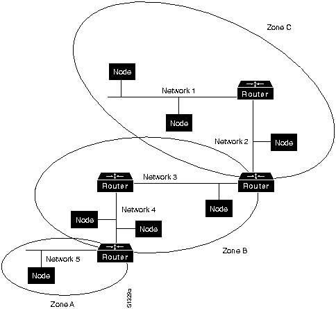
AppleTalk identifies several network entities. The most elemental is a node, which is simply any device connected to an AppleTalk network. The most common nodes are Macintosh computers and laser printers, but many other types of computers are also capable of AppleTalk communication, including IBM PCs, Digital Equipment Corporation VAX computers, and a variety of workstations. The next entity defined by AppleTalk is the network. An AppleTalk network is simply a single logical cable. Although the logical cable is frequently a single physical cable, some sites use bridges to interconnect several physical cables. Finally, an AppleTalk zone is a logical group of (possibly noncontiguous) networks. These AppleTalk entities are shown in Figure 16-3.
Figure 16-3 : AppleTalk Entities
Datagram Delivery Protocol (DDP)
AppleTalk's primary network-layer protocol is the Datagram Delivery Protocol (DDP). DDP provides connectionless service between network sockets. Sockets can be assigned either statically or dynamically.
AppleTalk addresses, which are administered by the DDP, consist of two components: a 16-bit network number and an 8-bit node number. The two components are usually written as decimal numbers, separated by a period (for example, 10.1 means network 10, node 1). When an 8-bit socket identifying a particular process is added to the network number and node number, a unique process on a network is specified.
AppleTalk Phase 2 distinguishes between nonextended and extended networks. In a nonextended network such as LocalTalk, each AppleTalk node number is unique. Nonextended networks were the sole network type defined in AppleTalk Phase 1. In an extended network such as EtherTalk and TokenTalk, each network number/node number combination is unique.
Zones are defined by the AppleTalk network manager during the router configuration process. Each node in an AppleTalk network belongs to a single specific zone. Extended networks can have multiple zones associated with them. Nodes on extended networks can belong to any single zone associated with the extended network.
AppleTalk's transport layer is implemented by several protocols: Routing Table Maintenance Protocol (RTMP), AppleTalk Update-Based Routing Protocol (AURP), AppleTalk Echo Protocol (AEP), AppleTalk Transaction Protocol (ATP), and Name Binding Protocol (NBP).
Routing Table Maintenance Protocol (RTMP)
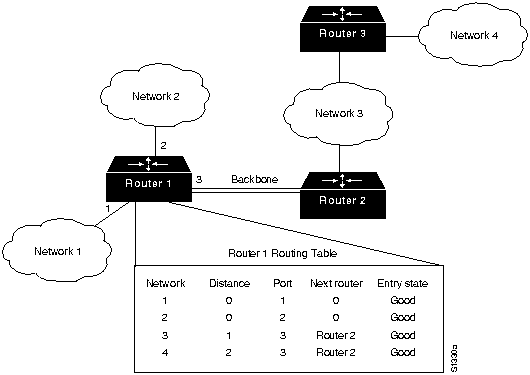
The protocol that establishes and maintains AppleTalk routing tables is called the Routing Table Maintenance Protocol (RTMP). RTMP routing tables contain an entry for each network that a datagram can reach. Each entry includes the router port that leads to the destination network, the node ID of the next router to receive the packet, the distance in hops to the destination network, and the current state of the entry (good, suspect, or bad). Periodic exchange of routing tables allows the routers in an internetwork to ensure that they supply current and consistent information. Figure 16-4 shows a sample RTMP table and the corresponding network architecture.
Figure 16-4 : Sample AppleTalk Routing Table
AppleTalk's Name Binding Protocol (NBP) associates AppleTalk names (expressed as network-visible entities, or NVEs) with addresses. An NVE is an AppleTalk network-addressable service, such as a socket. NVEs are associated with one or more entity names and attribute lists. Entity names are character strings such as printer@net1, while attribute lists specify NVE characteristics.
Named NVEs are associated with network addresses through the process of name binding. Name binding can be done when the user node is first started up, or dynamically, immediately before first use. NBP orchestrates the name binding process, which includes name registration, name confirmation, name deletion, and name lookup.
Zones allow name lookup in a group of logically related nodes. To look up names within a zone, an NBP lookup request is sent to a local router, which sends a broadcast request to all networks that have nodes belonging to the target zone. The Zone Information Protocol (ZIP) coordinates this effort.
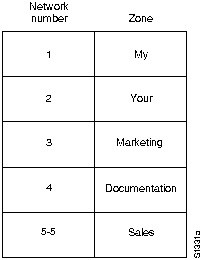
ZIP maintains network number to zone name mappings in zone information tables (ZITs). ZITs are stored in routers, which are the primary users of ZIP, but end nodes use ZIP during the startup process to choose their zone and to acquire internetwork zone information. ZIP uses RTMP routing tables to keep up with network topology changes. When ZIP finds a routing table entry that is not in the ZIT, it creates a new ZIT entry. Figure 16-5 shows a sample ZIT.
Figure 16-5 : Sample AppleTalk ZIT
AppleTalk Update-Based Routing Protocol
AppleTalk Update-Based Routing Protocol (AURP) allows a network administrator to connect two or more AppleTalk internetworks through a foreign network (such as Transmission Control Protocol/Internet Protocol [TCP/IP]) to form an AppleTalk wide-area network (WAN). The connection is called a tunnel, which functions as a single, virtual data link between the AppleTalk internetworks, as shown in Figure 16-6.
Figure 16-6 : AppleTalk Tunnel
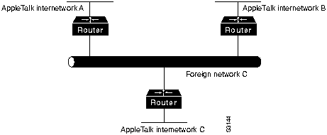
A router that connects an AppleTalk internetwork to a tunnel (that is, a router that runs AURP) is called an exterior router. The exterior router sends AppleTalk data packets and routing information through the foreign network by encapsulating the packets with the header information required by the foreign network system. The receiving exterior router removes the foreign header information and sends the packets out the appropriate interface. Packets are encapsulated in User Datagram Protocol (UDP) headers in the initial implementation of AURP.
When only two exterior routers are connected to a tunnel, that tunnel is called a point-to-point tunnel. When more than two exterior routers are connected to the tunnel, that tunnel is called a multipoint tunnel. If all exterior routers connected to a multipoint tunnel can send packets to each other, the tunnel is said to be fully connected. If one or more exterior routers are not aware of other exterior routers, the tunnel is said to be partially connected. Each exterior router functions both as an AppleTalk router within its local internetwork and as an end node in the foreign network that connects the AppleTalk internetworks.
The main function of AURP is to maintain accurate routing tables for the entire AppleTalk WAN by the exchange of routing information between exterior routers. In addition, AURP encapsulates AppleTalk data packets with the headers required by the foreign network.
AURP uses the principle of split horizons (which states that it is never useful to send information about a route back in the direction from which the information came) to limit the propagation of routing updates. For that reason, an exterior router sends routing information about only the networks that comprise its local internetwork to other exterior routers connected to the tunnel.
When an exterior router becomes aware of another exterior router on the tunnel, the two exterior routers exchange their lists of network numbers and associated zone information. Thereafter, an exterior router sends routing information only when the following events occur:
When an exterior router receives AppleTalk data packets or routing information that needs to be forwarded over the tunnel, the AURP module converts that information to AURP packets. The AURP packets are encapsulated in the header information required by the foreign network and sent over the tunnel to the destination exterior router, as shown in Figure 16-7.
Figure 16-7 : AURP Architectural Model
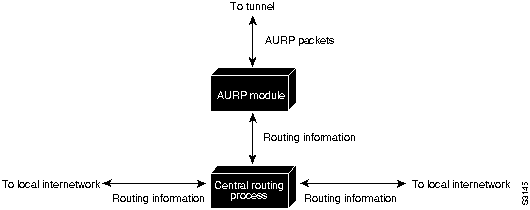
At the destination exterior router, the AURP module removes the headers required by the foreign system from the AURP packets and sends AppleTalk data packets to their final destination. The exterior router uses the AURP packets that contain routing information to update its routing information tables but does not propagate that information to any other exterior router.
AEP is an extremely simple protocol that generates packets that can be used to test the reachability of various network nodes.
AppleTalk Transaction Protocol (ATP)
ATP is suitable for transaction-based applications such as those found in banks or retail stores. ATP transactions consist of requests (from clients) and replies (from servers). Each request/reply pair has a particular transaction ID. Transactions occur between two socket clients. ATP uses exactly once (XO) and at-least-once (ALO) transactions. XO transactions are used in situations where performing the transaction more than once would be unacceptable. Banking transactions are examples of transactions that, if performed more than once, would result in invalid data.
ATP is capable of most important transport-layer functions, including data acknowledgment and retransmission, packet sequencing, and fragmentation and reassembly. ATP limits message segmentation to 8 packets, and ATP packets cannot contain more than 578 data bytes.
AppleTalk supports several upper-layer protocols:
|
|
Copyright 1988-1996 © Cisco Systems Inc.