Step 2 When the modem is successfully discovered, configure the modem automatically using the modem autoconfigure type modem-name line configuration command.
If you want to display the list of modems for which the router has entries, use the show modemcap modem-name. If you want to change a modem value that was returned from the show modemcap command, use the modemcap edit modem-name attribute value line configuration command.
For complete information on the use of these commands, refer to the Cisco IOS Access Services Configuration Guide and Access Services Command Reference.
Establishing a Reverse Telnet Session to a Modem
If you are running Cisco IOS Release 11.0 or earlier, you must establish a reverse Telnet session to configure a modem to communicate with a Cisco device. As long as you lock the DTE-side speed of the modem (see Table 14-5 for information on locking the modem speed), the modem will always communicate with the access server or router at the desired speed. Be certain that the speed of the Cisco device is configured prior to issuing commands to the modem via a reverse Telnet session. (See Table 14-5 for information on configuring the speed of the access server or router.)
To initiate a reverse Telnet session to your modem, perform the following steps:
Step 1 From your terminal, use the command
- telnet ip-address 20yy
- where ip-address is the IP address of any active, connected interface on the Cisco device, and yy is the line number to which the modem is connected. For example, the following command would connect you to the auxiliary port on a Cisco router with IP address 192.169.53.52:
telnet 192.169.53.52 2001
- Generally, a Telnet command of this kind can be issued from anywhere on the network that can ping the IP address in question.
Note On a Cisco router, port 01 is the auxiliary port. On a Cisco access server, the auxiliary port is last_tty+1, so on a 16-port access server, the auxiliary port is port 17. Use the show line EXEC command to make certain you are working with the correct line.
Step 2 If the connection is refused, there may already be a user connected to that port. Use the show users EXEC command to determine if the line is being used. If desired, the line can be cleared from the console using the clear line privileged EXEC command. When you are certain the line is not in use, attempt the Telnet connection again.
Step 3 If the connection is again refused, confirm that you have set modem control to modem inout for that line. See Table 14-2 for more information on configuring modem control on a line.
Step 4 If the connection is still refused, the modem might be asserting CD all of the time. Disconnect the modem from the line, establish a reverse Telnet session, and then connect the modem.
Step 5 After successfully making the Telnet connection, enter AT and make sure the modem replies with OK.
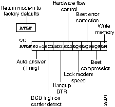
- Figure 14-1 shows a typical Hayes-compatible modem command string. Be certain to check the documentation for your specific modem to verify the exact syntax of these commands.
Figure 14-1 : Typical Hayes-Compatible Modem Command String
Interpreting show line Output
The output from the show line line-number EXEC command is useful when troubleshooting a modem-to-access server or router connection. Figure 14-2 shows the output from the show line command.
Figure 14-2 : show line Command Output
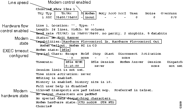
When connectivity problems occur, important output appears in the Modem State and the Modem Hardware State fields.
Note The Modem Hardware State field does not appear in the show line output for every platform. In certain cases, the indications for signal states will be shown in the Modem State field instead.
Table 14-1 shows typical Modem State and Modem Hardware State strings from the output of the show line command and explains the meaning of each state.
Table 14-1 : Modem and Modem Hardware States in show line Output
| Idle
|
CTS noDSR DTR RTS
|
These are the proper modem states for connections between an access server or router and a modem (when there is no incoming call). Output of any other kind generally indicates a problem.
|
| Ready
|
--
|
If the Modem State is Ready instead of Idle, there are three possibilities:
- Modem control is not configured on the access server or router. Configure the access server or router with the modem inout line configuration command.
- A session exists on the line. Use the show users EXEC command and use the clear line privileged EXEC command to stop the session if desired.
- DSR is high. There are two possible reasons for this:
- Cabling problems---If your connector uses DB-25 pin 6 and has no pin 8, you must move the pin from 6 to 8 or get the appropriate connector.
- Modem configured for DCD always high---The modem should be reconfigured to have DCD high only on CD.1 This is usually done with the &C1 modem command (see Figure 14-1), but check your modem documentation for the exact syntax for your modem.
- If your software does not support modem control, you must configure the access server line to which the modem is connected with the no exec line configuration command. Clear the line with the clear line privileged EXEC command, initiate a reverse Telnet session with the modem, and reconfigure the modem so that DCD is high only on CD.
- End the Telnet session by entering disconnect and reconfigure the access server line with the exec line configuration command.
|
| Ready
|
noCTS noDSR DTR RTS
|
There are four possibilities for the noCTS string appearing in the Modem Hardware State field:
- The modem is turned off.
- The modem is not connected to the access server properly. Check the cabling connections from the modem to the access server.
- Incorrect cabling (either rolled MDCE, or straight MDTE but without the pins moved). See Table 14-2 for information on the recommended cabling configuration.
- The modem is not configured for hardware flow control. Disable hardware flow control on the access server with the no flowcontrol hardware line configuration command and then enable hardware flow control on the modem via a Reverse Telnet session. (Consult your modem documentation and see the section "Establishing a Reverse Telnet Session to a Modem" earlier in this chapter.)
Reenable hardware flow control on the access server with the flowcontrol hardware line configuration command.
|
| Ready
|
CTS DSR DTR RTS
|
There are two possibilities for the presence of the DSR string instead of the noDSR string in the Modem Hardware State field:
- Incorrect cabling (either rolled MDCE, or straight MDTE but without the pins moved). See Table 14-2 for information on the recommended cabling configuration.
- The modem is configured for DCD always high. Reconfigure the modem so that DCD is only high on CD. This is usually done with the &C1 modem command (see Figure 14-1), but check your modem documentation for the exact syntax for your modem.
Configure the access server line to which the modem is connected with the no exec line configuration command. Clear the line with the clear line privileged EXEC command, initiate a reverse Telnet session with the modem, and reconfigure the modem so that DCD is high only on CD.
End the Telnet session by entering disconnect. Reconfigure the access server line with the exec line configuration command.
|
| Ready
|
CTS* DSR* DTR RTS2
|
If this string appears in the Modem Hardware State field, modem control is probably not enabled on the access server. Use the modem inout line configuration command to enable modem control on the line.
See Table 14-2 for more information on configuring modem control on an access server or router line.
|
1 CD=carrier detect
2 A "*" next to a signal indicates one of two things: the signal has changed within the last few seconds, or the signal is not being used by the modem control method selected.
No Connectivity between Modem and Router
Symptom: The connection between a modem and a Cisco access server or router does not work. Attempts to initiate a reverse Telnet session to the modem have no result, or the user receives a "Connection Refused by Foreign Host" message.
Note More specific symptoms for dialin connection problems are covered later in this chapter.
Table 14-2 outlines the problems that might cause this symptom and describes solutions to those problems.
Table 14-2 : Dialin: No Connectivity between Modem and Router
| Modem control is not enabled on the access server or router
|
Step 1 Use the show line EXEC command on the access server or router. The output for the auxiliary port should show "inout" or "RIisCD" in the Modem column. This indicates that modem control is enabled on the line of the access server or router.
- For an explanation of show line output, see the "Interpreting show line Output" section earlier in this chapter.
Step 2 Configure the line for modem control using the modem inout line configuration command. Modem control is now enabled on the access server.
- Note: Be certain to use the modem inout command and not the modem ri-is-cd command while the connectivity of the modem is in question. The latter command allows the line to accept incoming calls only. Outgoing calls will be refused, making it impossible to establish a Telnet session with the modem to configure it. If you want to enable the modem ri-is-cd command, do so only after you are certain the modem is functioning correctly.
|
| Incorrect cabling
|
Step 1 Check the cabling between the modem and the access server or router. Confirm that the modem is connected to the auxiliary port on the access server or router with a rolled RJ-45 cable and an MMOD DB-25 adapter. This cabling configuration is recommended and supported by Cisco for RJ-45 ports. (These connectors are typically labelled "Modem.")
Step 2 Use the show line EXEC command to verify that the cabling is correct. See the explanation of the show line command output in the section "Interpreting show line Output" earlier in this chapter.
|
| Hardware problem
|
Step 1 Verify that you are using the correct cabling and that all connections are good.
Step 2 Check all hardware for damage, including cabling (broken wires), adapters (loose pins), access server ports, and modem.
Step 3 See the "Troubleshooting Hardware and Booting Problems" chapter for more information on hardware troubleshooting.
|
Modem Does Not Dial
Symptom: Dialin sessions cannot be established because the modem does not dial properly.
Table 14-3 outlines the problems that might cause this symptom and describes solutions to those problems.
Table 14-3 : Dialin: Modem Does Not Dial
| Incorrect cabling
|
Step 1 Check the cabling between the modem and the access server or router. Confirm that the modem is connected to the auxiliary port on the access server or router with a rolled RJ-45 cable and an MMOD DB-25 adapter. This cabling configuration is recommended and supported by Cisco for RJ-45 ports. (These connectors are typically labelled "Modem.")
Step 2 Use the show line EXEC command to verify that the cabling is correct. See the explanation of the show line command output in the section "Interpreting show line Output" earlier in this chapter.
|
| Modem hardware problem
|
Check the modem's physical connection. Make sure the modem is on and is connected securely to the correct port. Make sure the transmit and receive indicator lights flash when the chat script is running.
|
| No interesting packets defined
|
Step 1 Use the show running-config privileged EXEC command to view the router configuration. Check the dialer-list interface configuration command entries to see which access lists, if any, are being used to define interesting traffic.
Step 2 Make sure that the access lists referenced by the dialer-list commands specify all traffic that should bring the link up (interesting traffic).
Step 3 If necessary, modify the access list commands so that they define the proper traffic as interesting.
|
| Missing chat script
|
Step 1 Use the debug chat privileged EXEC command to check if there is a chat script running.
Step 2 If there is no chat script running, use the start-chat privileged EXEC command or another appropriate command to start the chat script on the line.
For detailed information about creating and configuring chat scripts, refer to the Cisco IOS Access Services Configuration Guide and Access Services Command Reference.
|
| Bad chat script
|
Step 1 Establish a reverse Telnet session to the modem and step through each step of the chat script.
Step 2 Verify that the command response to each chat script step is correct.
Step 3 Fix any inconsistencies you find in the chat script.
For detailed information about creating and configuring chat scripts, refer to the Cisco IOS Access Services Configuration Guide and Access Services Command Reference.
|
Modem Does Not Answer
Symptom: When attempting to open a dialin connection to a modem, the modem does not answer the call.
Table 14-4 outlines the problems that might cause this symptom and describes solutions to those problems.
Table 14-4 : Dialin: Modem Does Not Answer
| Incorrect cabling
|
Step 1 Check the cabling between the modem and the access server or router. Confirm that the modem is connected to the auxiliary port on the access server or router with a rolled RJ-45 cable and an MMOD DB-25 adapter. This cabling configuration is recommended and supported by Cisco for RJ-45 ports. (These connectors are typically labeled "Modem.")
Step 2 Use the show line EXEC command to verify that the cabling is correct. See the explanation of the show line command output in the section "Interpreting show line Output" earlier in this chapter.
|
| Modem control not enabled on access server or router
|
Step 1 Observe the remote modem to see if it is receiving a DTR signal from the router. Most modems have a DTR indicator light. Check the modem documentation to interpret the indicator lights.
Step 2 If the DTR indicator light is on, the modem is seeing a DTR signal from the router. You can also enter the show line EXEC command to check for DTR. If the modem hardware state shows the string noDTR, then the router is configured to hold DTR low and the modem is not seeing a DTR signal.
Step 3 Configure modem control using either the modem inout or the modem ri-is-cd line configuration command.
|
| Misconfigured dialer map commands
|
Step 1 Use the show running-config privileged EXEC command to view the router configuration. Check all dialer map statements to make sure they are configured correctly.
Step 2 Correct dialer map statements as necessary, making certain that all options are specified properly.
For detailed information on configuring dialer maps, refer to the Cisco IOS Wide-Area Networking Configuration Guide and Wide-Area Networking Command Reference.
|
| Remote modem not set to auto-answer
|
Step 1 Check the remote modem to see if it is set to auto-answer. Usually, an AA indicator light will be on when auto-answer is set.
Step 2 Set the remote modem to auto-answer if it is not already set. To find out how to verify and change the modem's settings, refer to your modem documentation.
|
| Wrong telephone line attached to remote modem
|
Step 1 Make sure you are using the correct telephone line. Replace the remote modem with a telephone and call again. If the phone rings, you are using the correct telephone line.
Step 2 Contact the telephone company to make sure that the line is good.
|
| Remote modem not attached to a router
|
Step 1 Make sure the remote modem is attached to a router or other device that is asserting DTR.
Step 2 Most modems have an LED indicator for DTR. Check to make sure this indicator comes on.
|
Modem Hangs Up Shortly After Connecting
Symptom: A dialin connection is successful but the modem hangs up after 30 to 90 seconds.
Table 14-5 outlines the problems that might cause this symptom and describes solutions to those problems.
Table 14-5 : Dialin: Modem Hangs Up Shortly After Connecting
| Modem speed setting is not locked
|
Step 1 Use the show line EXEC command on the access server or router. The output for the auxiliary port should indicate the currently configured Tx1 and Rx2 speeds.
- For an explanation of the output from the show line command, see the section "Interpreting show line Output" earlier in this chapter.
Step 2 If the line is not configured to the correct speed, use the speed line configuration command to set the line speed on the access server or router line. Set the value to the highest speed in common between the modem and the access server or router port.
- Note: If for some reason you cannot use flow control, limit the line speed to 9600 bps. Faster speeds are likely to result in lost data.
Step 3 Use the show line EXEC command again and confirm that the line speed is set to the desired value.
Step 4 When you are certain that the access server or router line is configured for the desired speed, initiate a reverse Telnet session to the modem on that line. For more information, see the section "Establishing a Reverse Telnet Session to a Modem" earlier in this chapter.
Step 5 Use a modem command string that includes the lock DTE speed command for your modem. See your modem documentation for exact configuration command syntax.
- Note: The lock DTE speed command, which might also be referred to as port rate adjust or buffered mode, is often related to the way in which the modem handles error correction. This command varies widely between modems.
- Locking the modem speed ensures that the modem always communicates with the Cisco access server or router at the speed configured on the Cisco auxiliary port. If this command is not used, the modem will revert to the speed of the data link (the telephone line) instead of communicating at the speed configured on the access server.
|
| Modem control is not enabled on the access server or router
|
Step 1 Use the show line EXEC command on the access server or router. The output for the auxiliary port should show "inout" or "RIisCD" in the Modem column. This indicates that modem control is enabled on the line of the access server or router.
- For an explanation of the show line output, see the "Interpreting show line Output" section earlier in this chapter.
Step 2 Configure the line for modem control using the modem inout line configuration command. Modem control is now enabled on the access server.
- Note: Be certain to use the modem inout command instead of the modem ri-is-cd command while the connectivity of the modem is in question. The latter command allows the line to accept incoming calls only. Outgoing calls will be refused, making it impossible to establish a Telnet session with the modem to configure it. If you want to enable the modem ri-is-cd command, do so only after you are certain the modem is functioning correctly.
|
| PPP authentication fails
|
Step 1 Use the debug ppp chap privileged EXEC command to see if PPP authentication was successful. Check the output for the phrase "Passed authentication with remote." If you see this output, authentication was successful.
Step 2 If PPP authentication was not successful, verify the username and password configured on the router. The username and password you enter must be identical to those configured on the router.
- Note: Usernames and passwords are case-sensitive.
|
| Local router not waiting long enough to connect
|
Step 1 Use the show dialer EXEC command to see the configured dialer timeout. A timeout value of less than 120 seconds will not be long enough.
Step 2 Configure the local router to wait longer for the connection. Use the dialer wait-for-carrier-time seconds to the configuration. Make sure you specify at least a 120-second timeout.
|
| Chat script problem
|
Step 1 Enter the debug chat privileged EXEC command. If you see the output "Success" at the end of the chat script, the chat script completed successfully.
Step 2 Make the timeout in the chat script longer at the point where it fails.
Step 3 If the problem persists, verify that the command response to each chat script step is correct. Open a reverse Telnet session to the modem and step through the chat script.
Step 4 Fix any inconsistencies you find in the chat script.
For detailed information about creating and configuring chat scripts, refer to the Cisco IOS Access Services Configuration Guide and Access Services Command Reference.
|
1 Tx=transmit
2 Rx=receive
Dialin Client Receives No EXEC Prompt
Symptom: A remote dialin client opens a session and appears to be connected, but the user does not receive an EXEC prompt (for example, a Username or Router> prompt).
Table 14-6 outlines the problems that might cause this symptom and describes solutions to those problems.
Table 14-6 : Dialin: Dialin Client Receives No EXEC Prompt
| Autoselect is enabled on the line
|
Attempt to access EXEC mode by issuing a carriage return.
|
| Line is configured with the no exec command
|
Step 1 Use the show line EXEC command to view the status of the appropriate line.
- Check the Capabilities field to see if it says "EXEC suppressed." If this is the case, the no exec line configuration command is enabled.
Step 2 Configure the exec line configuration command on the line to allow EXEC sessions to be initiated.
|
| Flow control is not enabled, is enabled only on one device (either DTE or DCE), or is misconfigured
|
Step 1 Use the show line aux-line-number EXEC command and look for the following in the Capabilities field (see Figure 14-2):
Capabilities: Hardware Flowcontrol In, Hardware Flowcontrol Out...
- If there is no mention of hardware flow control in this field, hardware flow control is not enabled on the line. Hardware flow control for access server-to-modem connections is recommended.
- For an explanation of the output from the show line command, see the "Interpreting show line Output" section earlier in this chapter.
Step 2 Configure hardware flow control on the line using the flowcontrol hardware line configuration command.
- Note: If for some reason you cannot use flow control, limit the line speed to 9600 bps. Faster speeds are likely to result in lost data.
Step 3 After enabling hardware flow control on the access server or router line, initiate a reverse Telnet session to the modem via that line. For more information, see the section "Establishing a Reverse Telnet Session to a Modem" earlier in this chapter.
Step 4 Use a modem command string that includes the RTS/CTS Flow command for your modem. This command ensures that the modem is using the same method of flow control (that is, hardware flow control) as the Cisco access server or router. See your modem documentation for exact configuration command syntax. Figure 14-1 shows the hardware flow control command string for a Hayes-compatible modem.
|
| Modem speed setting is not locked
|
Step 1 Use the show line EXEC command on the access server or router. The output for the auxiliary port should indicate the currently configured Tx and Rx speeds.
- For an explanation of the output of the show line command, see the "Interpreting show line Output" section earlier in this chapter.
Step 2 If the line is not configured to the correct speed, use the speed line configuration command to set the line speed on the access server or router line. Set the value to the highest speed in common between the modem and the access server or router port.
- Note: If for some reason you cannot use flow control, limit the line speed to 9600 bps. Faster speeds are likely to result in lost data.
Step 3 Use the show line EXEC command again and confirm that the line speed is set to the desired value.
Step 4 When you are certain that the access server or router line is configured for the desired speed, initiate a reverse Telnet session to the modem via that line. For more information, see the section "Establishing a Reverse Telnet Session to a Modem" earlier in this chapter.
Step 5 Use a modem command string that includes the lock DTE speed command for your modem. See your modem documentation for exact configuration command syntax.
- Note: The lock DTE speed command, which might also be referred to as port rate adjust or buffered mode, is often related to the way in which the modem handles error correction. This command varies widely between modems.
- Locking the modem speed ensures that the modem always communicates with the Cisco access server or router at the speed configured on the Cisco auxiliary port. If this command is not used, the modem will revert to the speed of the data link (the telephone line) instead of communicating at the speed configured on the access server.
|
Dialin Session Sees "Garbage"
Symptom: Attempts to establish remote dialin sessions over a modem to a Cisco access server or router return "garbage" and ultimately result in no connection to the remote site. Users might see a "Connection Closed by Foreign Host" message.
Table 14-7 outlines the problems that might cause this symptom and describes solutions to those problems.
Table 14-7 : Dialin: Dialin Session Sees "Garbage"
| Modem speed setting is not locked
|
Step 1 Use the show line EXEC command on the access server or router. The output for the auxiliary port should indicate the currently configured Tx and Rx speeds.
- For an explanation of the output of the show line command, see the "Interpreting show line Output" section earlier in this chapter.
Step 2 If the line is not configured to the correct speed, use the speed line configuration command to set the line speed on the access server or router line. Set the value to the highest speed in common between the modem and the access server or router port.
- Note: If for some reason you cannot use flow control, limit the line speed to 9600 bps. Faster speeds are likely to result in lost data.
Step 3 Use the show line EXEC command again and confirm that the line speed is set to the desired value.
Step 4 When you are certain that the access server or router line is configured for the desired speed, initiate a reverse Telnet session to the modem via that line. For more information, see the section "Establishing a Reverse Telnet Session to a Modem."
Step 5 Use a modem command string that includes the lock DTE speed command for your modem. See your modem documentation for exact configuration command syntax.
- Note: The lock DTE speed command, which might also be referred to as port rate adjust or buffered mode, is often related to the way in which the modem handles error correction. This command varies widely between modems.
- Locking the modem speed ensures that the modem always communicates with the Cisco access server or router at the speed configured on the Cisco auxiliary port. If this command is not used, the modem will revert to the speed of the data link (the telephone line) instead of communicating at the speed configured on the access server.
|
Dialin Session Ends Up in Existing Session
Symptom: Remote dialin session ends up in an already existing session initiated by another user. That is, instead of getting a login prompt, a dialin user sees a session established by another user (which might be a UNIX command prompt, a text editor session, and so forth).
Table 14-8 outlines the problems that might cause this symptom and describes solutions to those problems.
Table 14-8 : Dialin: Dialin Session Ends up in Existing Session
| Modem configured for DCD always high
|
Step 1 The modem should be reconfigured to have DCD high only on CD1. This is usually done with the &C1 modem command string (see Figure 14-1), but check your modem documentation for the exact syntax for your modem.
Step 2 You might have to configure the access server line to which the modem is connected with the no exec line configuration command. Clear the line with the clear line privileged EXEC command, initiate a reverse Telnet session with the modem, and reconfigure the modem so that DCD is high only on CD.
Step 3 End the Telnet session by entering disconnect and reconfigure the access server line with the exec line configuration command.
|
| Modem control is not enabled on the access server or router
|
Step 1 Use the show line EXEC command on the access server or router. The output for the auxiliary port should show "inout" or "RIisCD" in the Modem column. This indicates that modem control is enabled on the line of the access server or router.
- For an explanation of the show line output, see the "Interpreting show line Output" section earlier in this chapter.
Step 2 Configure the line for modem control using the modem inout line configuration command. Modem control is now enabled on the access server.
- Note: Be certain to use the modem inout command instead of the modem ri-is-cd command while the connectivity of the modem is in question. The latter command allows the line to accept incoming calls only. Outgoing calls will be refused, making it impossible to establish a Telnet session with the modem to configure it. If you want to enable the modem ri-is-cd command, do so only after you are certain the modem is functioning correctly.
|
| Incorrect cabling
|
Step 1 Check the cabling between the modem and the access server or router. Confirm that the modem is connected to the auxiliary port on the access server or router with a rolled RJ-45 cable and an MMOD DB-25 adapter. This cabling configuration is recommended and supported by Cisco for RJ-45 ports. (These connectors are typically labelled "Modem.")
Step 2 Use the show line EXEC command to verify that the cabling is correct. See the explanation of the show line command output in the section "Interpreting show line Output" earlier in this chapter.
|
1 CD=Carrier Detect
Modem Cannot Send or Receive Data
Symptom: After a dialin connection is established, a modem cannot send or receive data of any kind.
Table 14-9 outlines the problems that might cause this symptom and describes solutions to those problems.
Table 14-9 : Dialin: Modem Cannot Send or Receive Data
| Modem speed setting is not locked
|
Step 1 Use the show line EXEC command on the access server or router. The output for the auxiliary port should indicate the currently configured Tx and Rx speeds.
- For an explanation of the output of the show line command, see the "Interpreting show line Output" section earlier in this chapter.
Step 2 If the line is not configured to the correct speed, use the speed line configuration command to set the line speed on the access server or router line. Set the value to the highest speed in common between the modem and the access server or router port.
- Note: If for some reason you cannot use flow control, limit the line speed to 9600 bps. Faster speeds are likely to result in lost data.
Step 3 Use the show line EXEC command again and confirm that the line speed is set to the desired value.
Step 4 When you are certain that the access server or router line is configured for the desired speed, initiate a reverse Telnet session to the modem via that line. For more information, see the section "Establishing a Reverse Telnet Session to a Modem" earlier in this chapter.
Step 5 Use a modem command string that includes the lock DTE speed command for your modem. See your modem documentation for exact configuration command syntax.
- Note: The lock DTE speed command, which might also be referred to as port rate adjust or buffered mode, is often related to the way in which the modem handles error correction. This command varies widely between modems.
- Locking the modem speed ensures that the modem always communicates with the Cisco access server or router at the speed configured on the Cisco auxiliary port. If this command is not used, the modem will revert to the speed of the data link (the telephone line) instead of communicating at the speed configured on the access server.
|
| Hardware flow control not configured on local or remote modem or router
|
Step 1 Use the show line aux-line-number EXEC command and look for the following in the Capabilities field (see Figure 14-2):
Capabilities: Hardware Flowcontrol In, Hardware Flowcontrol Out...
- If there is no mention of hardware flow control in this field, hardware flow control is not enabled on the line. Hardware flow control for access server-to-modem connections is recommended.
- For an explanation of the output of the show line command, see the section "Interpreting show line Output" earlier in this chapter.
Step 2 Configure hardware flow control on the line using the flowcontrol hardware line configuration command.
- Note: If for some reason you cannot use flow control, limit the line speed to 9600 bps. Faster speeds are likely to result in lost data.
Step 3 After enabling hardware flow control on the access server or router line, initiate a reverse Telnet session to the modem via that line. For more information, see the section "Establishing a Reverse Telnet Session to a Modem."
Step 4 Use a modem command string that includes the RTS/CTS Flow command for your modem. This command ensures that the modem is using the same method of flow control (that is, hardware flow control) as the Cisco access server or router. See your modem documentation for exact configuration command syntax. Figure 14-1 shows the hardware flow control command string for a Hayes-compatible modem.
|
| Misconfigured dialer map commands
|
Step 1 Use the show running-config privileged EXEC command to view the router configuration. Check the dialer map command entries to see if the broadcast keyword is specified.
Step 2 If the keyword is missing, add it to the configuration.
Step 3 Make sure that dialer map commands specify the correct next hop addresses.
Step 4 If the next hop address is incorrect, change it using the dialer map command.
Step 5 Make sure that all other options in dialer map commands are correctly specified for the protocol you are using.
|
| Old PC UART problem
|
This problem only applies to PC-to-router dialin connections.
Step 1 Use the terminal download command at the EXEC prompt before you Telnet.
Step 2 If the problem persists, use the DOS program "MSD" to see what PC UART is on your comm port. Older PC UARTs, like the 8250, can't run at speeds over 19200 bps.
Step 3 If you have an older UART, try lowering your connection speed or get a faster serial card for your PC.
|
| Problem with dialing modem
|
Make sure that the dialing modem is operational and is securely connected to the correct port. See if another modem works when connected to the same port.
|
Modem Cannot Send or Receive IP Data
Symptom: After a dialin connection is established, a modem cannot send or receive IP data.
Note For general problems associated with a modem that cannot send or receive data, refer to the section "Modem Cannot Send or Receive Data" earlier in this chapter.
For information on troubleshooting IP problems not specific to dialin connections, refer to the "Troubleshooting TCP/IP" chapter.
Table 14-10 outlines the problems that might cause this symptom and describes solutions to those problems.
Table 14-10 : Dialin: Modem Cannot Send or Receive IP Data
| IP routing not configured on local or remote router
|
Make sure that IP routing is enabled on the local and remote routers. For detailed information about configuring IP routing, refer to the Cisco IOS Network Protocols Configuration Guide, Part 1.
|
| No default gateway specified on PC
|
Step 1 Use the show slip EXEC command and make sure that the specified IP address is the same as the default gateway specification on the PC.
Step 2 Check the specified default gateway address on the PC. If the IP address is not correct, specify the correct address. For instructions on verifying and changing the default gateway address on the workstation, refer to the vendor documentation.
|
| Hardware flow control not configured on local or remote modem or router
|
Step 1 Use the show line aux-line-number EXEC command and look for the following in the Capabilities field (see Figure 14-2):
Capabilities: Hardware Flowcontrol In, Hardware Flowcontrol Out...
- If there is no mention of hardware flow control in this field, hardware flow control is not enabled on the line. Hardware flow control for access server-to-modem connections is recommended.
- For an explanation of the output of the show line command, see the "Interpreting show line Output" section earlier in this chapter.
Step 2 Configure hardware flow control on the line using the flowcontrol hardware line configuration command.
- Note: If for some reason you cannot use flow control, limit the line speed to 9600 bps. Faster speeds are likely to result in lost data.
Step 3 After enabling hardware flow control on the access server or router line, initiate a reverse Telnet session to the modem via that line. For more information, see the section "Establishing a Reverse Telnet Session to a Modem."
Step 4 Use a modem command string that includes the RTS/CTS Flow command for your modem. This command ensures that the modem is using the same method of flow control (that is, hardware flow control) as the Cisco access server or router. See your modem documentation for exact configuration command syntax. Figure 14-1 shows the hardware flow control command string for a Hayes-compatible modem.
|
| Misconfigured dialer map commands
|
Step 1 Use the show running-config privileged EXEC command to view the router configuration. Check the dialer map command entries to see if the broadcast keyword is specified.
Step 2 If the broadcast keyword is missing, add it to the configuration.
|
| Static routes not configured
|
Step 1 Use the show ip route privileged EXEC command to see if there is a static route to the remote network in the routing table.
Step 2 If there is not a static route to the remote network, configure one using the ip route command. The static route should point to the remote network via the next hop in the dialer map.
|
| DNS server not specified on router or workstation
|
Step 1 Check to see if the workstation and router both have DNS information specified. On the router, use the show running-config privileged EXEC command to see if DNS is configured. For information on verifying the workstation configuration, refer to the vendor documentation.
Step 2 If the router and workstation are not configured to use DNS, use the ip domain-lookup, ip domain-name, and ip name-server commands to configure the router.
- Configure a DNS server address in the TCP/IP software on the PC. For more information, refer to the vendor documentation.
|
Modem Cannot Send or Receive IPX Data
Symptom: After a dialin connection is established, a modem cannot send or receive Novell IPX data.
Note For general problems associated with a modem that cannot send or receive data, refer to the section "Modem Cannot Send or Receive Data" earlier in this chapter.
For information on troubleshooting Novell IPX problems not specific to dialin connections, refer to the "Troubleshooting Novell IPX" chapter.
Table 14-11 outlines the problems that might cause this symptom and describes solutions to those problems.
Table 14-11 : Dialin: Modem Cannot Send or Receive IPX Data
| IPX not enabled on the router
|
Make sure that IPX routing is enabled on the router. For detailed information on enabling IPX routing, refer to the Cisco IOS Network Protocols Configuration Guide, Part 1.
|
| Incorrect Ethernet encapsulation
|
Step 1 Enter the show ipx servers privileged EXEC command on your router. If the router is not in the listing, the Ethernet encapsulation might be incorrect.
Step 2 Configure the correct Ethernet encapsulation on the router's Ethernet port using the ipx network network encapsulation encapsulation-type interface configuration command. The encapsulation must be the same as your server.
|
| IPX stack not installed correctly on PC
|
This problem applies only to PC-to-router dialin connections.
Make sure that the IPX software is properly installed on the PC. For more information on installing the IPX stack, refer to the vendor documentation.
|
Modem Does Not Disconnect Properly
Symptom: Modem does not disconnect properly. Connections to the modem do not terminate when the quit command is entered.
Table 14-12 outlines the problems that might cause this symptom and describes solutions to those problems.
Table 14-12 : Dialin: Modem Does Not Disconnect Properly
| Modem is not sensing DTR
|
Enter the Hangup DTR modem command string. This command tells the modem to drop carrier when the DTR signal is no longer being received.
On a Hayes-compatible modem the &D3 string is commonly used to configure Hangup DTR on the modem, as shown in Figure 14-1. For the exact syntax of this command, see the documentation for your modem.
|
| Modem control is not enabled on the router or access server
|
Step 1 Use the show line EXEC command on the access server or router. The output for the auxiliary port should show "inout" or "RIisCD" in the Modem column. This indicates that modem control is enabled on the line of the access server or router.
- For an explanation of the show line output, see the "Interpreting show line Output" section earlier in this chapter.
Step 2 Configure the line for modem control using the modem inout line configuration command. Modem control is now enabled on the access server.
- Note: Be certain to use the modem inout command instead of the modem ri-is-cd command while the connectivity of the modem is in question. The latter command allows the line to accept incoming calls only. Outgoing calls will be refused, making it impossible to establish a Telnet session with the modem to configure it. If you want to enable the modem ri-is-cd command, do so only after you are certain the modem is functioning correctly.
|
Link Goes Down Too Soon
Symptom: After a dialin connection is established, the link goes down again too quickly.
Table 14-3 outlines the problems that might cause this symptom and describes solutions to those problems.
Table 14-13 : Dialin: Link Goes Down Too Soon
| Dialer timeout is too short
|
Step 1 Use the show running-config privileged EXEC command to view the router configuration. Check the value configured with the dialer idle-timeout command.
Step 2 Increase the timeout value using the dialer idle-timeout seconds command. The default is 120 seconds.
|
| Dialer lists are too restrictive
|
Step 1 Use the show running-config privileged EXEC command to view the router configuration. Check the access lists referenced by dialer list commands.
Step 2 Make sure the access lists describe all the traffic that should keep the link active. Reconfigure the access lists to include additional traffic if necessary.
|
Link Does Not Go Down or Stays Up Too Long
Symptom: After a dialin connection is established, the link stays up indefinitely or stays up for too long in an idle state.
Table 14-14 outlines the problems that might cause this symptom and describes solutions to those problems.
Table 14-14 : Dialin: Link Does Not Go Down or Stays Up Too Long
| Dialer lists not restrictive enough
|
Step 1 Use the show running-config privileged EXEC command to view the router configuration. Check the access lists referenced by dialer list commands.
Step 2 Make sure the access lists do not describe traffic that should not keep the link active. Reconfigure the access lists to exclude uninteresting traffic if necessary.
|
| Modems misconfigured
|
Make sure the local and remote modems are properly configured. In particular, both modems should be configured to disconnect on loss of DTR (Hangup DTR).
On a Hayes-compatible modem the &D3 string is commonly used to configure Hangup DTR on the modem, as shown in Figure 14-1. For the exact syntax of this command, see the documentation for your modem.
|
Poor Performance
Symptom: After a dialin connection is established, performance over the link is slow or unreliable, often due to a high rate of data loss.
Table 14-15 outlines the problems that might cause this symptom and describes solutions to those problems.
Table 14-15 : Dialin: Poor Performance
| Error correction is not configured on the modem
|
Make certain the modem is configured for error correction. For the exact syntax of the command, see your modem documentation.
|
| Flow control is not enabled, is enabled only on one device (either DTE or DCE), or is misconfigured
|
Step 1 Use the show line aux-line-number EXEC command and look for the following in the Capabilities field (see Figure 14-2):
Capabilities: Hardware Flowcontrol In, Hardware Flowcontrol Out...
- If there is no mention of hardware flow control in this field, hardware flow control is not enabled on the line. Hardware flow control for access server-to-modem connections is recommended.
- For an explanation of the output of the show line command, see the "Interpreting show line Output" section earlier in this chapter.
Step 2 Configure hardware flow control on the line using the flowcontrol hardware line configuration command.
- Note: If for some reason you cannot use flow control, limit the line speed to 9600 bps. Faster speeds are likely to result in lost data.
Step 3 After enabling hardware flow control on the access server or router line, initiate a reverse Telnet session to the modem via that line. For more information, see the section "Establishing a Reverse Telnet Session to a Modem."
Step 4 Use a modem command string that includes the RTS/CTS Flow command for your modem. This command ensures that the modem is using the same method of flow control (that is, hardware flow control) as the Cisco access server or router. See your modem documentation for exact configuration command syntax. Figure 14-1 shows the hardware flow control command string for a Hayes-compatible modem.
|
| Congestion or line noise
|
Step 1 If the network is congested, dial-up connections can freeze for a few seconds. The only solution is to reduce congestion on the network by increasing bandwidth or redesigning the network.
Step 2 Line noise can also freeze up a dialup connection. For information on how to account for line noise for your modem, refer to the vendor documentation.
|
| Old PC UART
|
This problem applies only to PC-to-router dialin connections.
Step 1 Use the DOS program "MSD" to see what PC UART is on your comm port. Older PC UARTs, like the 8250, cannot run at speeds over 19200 bps.
Step 2 If you have an older UART, try lowering your connection speed or get a faster serial card for your PC.
|
Copyright 1988-1996 © Cisco Systems Inc.
