|
|
This chapter describes the cable television (CATV) headend site requirements and considerations for installing the Cisco uBR7246. The chapter contains the following sections:
Before installing your Cisco uBR7246, you should analyze the radio frequency (RF) setup at the CATV headend installation site and configure the analog RF signals for the interaction with digital data. This chapter guides you through the process of configuring the RF and digital data at the headend for optimal performance.
Your cable customers connect to the headend using the standard hybrid fiber coaxial (HFC) cable network and a cable modem connected to their computer. These connections are enabled by the cable modem cards installed in your Cisco uBR7246.
Figure 4-1 illustrates the connection from the subscriber to the headend, and the headend to the Internet using a Cisco uBR7246 universal broadband router. The digital data is transmitted and received on both sides of this connection using Internet Protocol (IP).

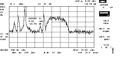
Step 1 Connect a spectrum analyzer to the RF line. Set the resolution bandwidth to 100 kHz and the video bandwidth to 30 kHz. Your analyzer should display a raw RF signal similar to the one shown in Figure 4-2.

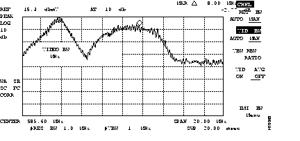
Step 2 Adjust the spectrum analyzer to set the resolution bandwidth to 1.0 MHz and the video bandwidth to 1 MHz. Your analyzer will now display an intermediate modified RF signal similar to the one shown in Figure 4-3.

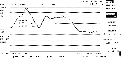
Step 3 Using the video averaging function on the spectrum analyzer, set video averaging to count 100. Add 5 dB to the digital amplitude of the RF signal to adjust for correct channel power.

Step 4 Verify that your headend RF specifications match the recommended settings listed in Table 4-1. Record your headend settings in the last column in
Table 4-1 while you verify them. This will assist in troubleshooting the Cisco uBR7246 installation later in the process.
| Specification | MCNS Specifications1 | Recommended Settings2 | Your Headend Settings |
|---|---|---|---|
| System/Channel | |||
| > 15 dB (QPSK)4 > 18 dB (16 QAM)4 | ||
| > 25 dB (64 QAM)4 > 33 dB (256 QAM)4 | ||
|
< -26 dBc6 | < -26 dBc | |
|
< -50 dBc | < -50 dBc | |
|
0.5 dB in 6 MHz | 0.5 dB in 6 MHz | |
|
75 ns7 in 6 MHz | 75 ns in 6 MHz | |
| Digital Signal Levels | |||
|
8 to 55 dBmV | 35 to 55 dBmV | |
|
- | -8, 0, or 8 dBmV | |
|
-15 to 15 dBmV | -15 to 15 dBmV | |
|
-6 dB or -10 dB | -6 dB or -10 dB |
Once you have analyzed and adjusted the RF signal according to the steps outlined on the preceding pages, proceed to the next section "Digital Data Configuration."
Once you have configured the RF signal, you must configure the digital data signal that will be carried between the Cisco uBR7246 universal broadband router and cable modems.
You should install a Cisco cable modem at the headend to verify the digital data configuration. For instructions on how to install a Cisco cable modem, refer to the Cisco Cable Modem Installation and Configuration Guide (Document Number 78-4769-xx). This document accompanies every Cisco cable modem that is shipped from the factory.
The output of the Cisco uBR7246 universal broadband router is in standard intermediate frequency (IF) signals. IF signals are converted to RF signals through an upconverter. Upconverter output levels should be set to carry the digital signal data at 6 dB or 10 dB below the adjacent analog video signal. The value chosen is at each cable operator's discretion.
Careful system design and operation can prevent potentially serious intermittent performance problems across your cable modem network. Each cable operator should make use of the following guidelines and practices to ensure reliable operation of any QAM 64-based digital network:
For example, if your headend overdrives the fibre optic lasers, in either the upstream or downstream path, clipping (the self-protecting, automatic shutoff feature in fiber-optic lasers) can occur. Fiber optic clipping leads to damaged signal integrity. This signal damage is not visible on an analog video signal, but it can completely disrupt the digital transmission path. Digital signals with forward error correction (FEC) are susceptible to changes in signal level on the order of 0.1 dB. If there is no amplitude margin available in the transmission path between the headend and any one cable modem, the typical signal level variations of a properly functioning cable system (3 to 6 dB) can create intermittent service outages that are difficult to isolate.
Typical CATV measurement equipment, such as spectrum analyzers, measure to an accuracy of +/- 1.0 dB. However, field meters measure to an accuracy of +/- 3dB; therefore, maintaining 6 dB margins above the minimum levels can provide reliable long term service.
This section describes the interaction of digital and analog RF data as both signals are carried on the HFC network.
Two-way digital data signals are more susceptible than one-way video signals to stresses in the overall condition of the HFC network. Degradation in video signal quality might not be noticed, but when two-way digital signals share the network with video signals, digital signals might be hampered by the following types of network variations:
|
|