|
|

This chapter provides pinouts for Cisco 3800 connections, and contains the following sections:
Four DB-25 connectors (see Figure 4-1) provide serial data interface ports with the pinout described in Table 4-1.

| Pin | Signal Name | Direction | Description |
|---|---|---|---|
| 1 | GND | - | Chassis Ground |
| 2 | TxDA | In | Transmit Data A |
| 3 | RxDA | Out | Receive Data A |
| 4 | RTSA | In | Request To Send A |
| 5 | CTSA | Out | Clear To Send A |
| 6 | DSRA | Out | Data Set Ready A |
| 7 | SIG-GROUND | - | Signal Ground |
| 8 | DCDA | Out | Carrier Detect A |
| 9 | RxCB | Out | Receive Clock B |
| 10 | DCDB | Out | Carrier Detect B |
| 11 | TTB | In | Terminal Timing B |
| 12 | TxCB | Out | Transmit Clock B |
| 13 | CTSB | Out | Clear To Send B |
| 14 | TxDB | In | Transmit Data B |
| 15 | TxCA | Out | Transmit Clock A |
| 16 | RxDB | Out | Receive Data B |
| 17 | RxCA | Out | Receive Clock A |
| 18 | LL | In | Local Loopback |
| 19 | RTSB | In | Request To Send B |
| 20 | DTRA | In | Data Terminal Ready A |
| 21 | RL | In | Remote Loopback |
| 22 | DSRB | Out | Data Set Ready B |
| 23 | DTRB | In | Request Terminal Ready B |
| 24 | TTA | In | Terminal Timing A |
| 25 | TM | Out | Test Mode |
The RJ-45 connector labeled SRV connects a service and maintenance terminal for configuring the Cisco 3800, optional cards, or an external modem. (See Figure 4-2.) This port has two asynchronous channels: channel 1 is the console port providing direct or dial-in access to the Combo card through an external modem; channel 2 is the debug port used only at the factory. Both channels are DTEs. See Table 4-2 for service and maintenance port pinouts.

| Pin | Signal Name | Direction | Description |
|---|---|---|---|
| 1 | RXD1 | In | Receive Data 1 |
| 2 | CD1 | In | Carrier Detect 1 |
| 3 | DTR1 | Out | Data Terminal Ready 1 |
| 4 | GND | - | Ground |
| 5 | GND | - | Ground |
| 6 | RXD2 | In | Receive Data 2 |
| 7 | TXD2 | Out | Transmit Data 2 |
| 8 | TXD1 | Out | Transmit Data 1 |
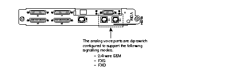
Two RJ-45 connectors labeled V0 and V1 are analog voice ports. (See Figure 4-3.) They can be configured as E&M, FXS or FXO lines using DIP switches SW1, SW2, and SW3 on the Combo card as described in the chapter "Installing Cisco 3800 Cards." Table 4-3 and Table 4-4 list the pinouts for the setting selected.

| Pin | E&M Signal | Direction |
|---|---|---|
| 1 | SB | Out |
| 2 | M | In |
| 3 | R | In |
| 4 | R1 | Out |
| 5 | T1 | Out |
| 6 | T | In |
| 7 | E | Out |
| 8 | SG | Out |
| Pin | FXS Signal | Direction | FXO Signal | Direction |
|---|---|---|---|---|
| 1 | - | - | - | - |
| 2 | - | - | - | - |
| 3 | - | - | - | - |
| 4 | T | I/O(+) | R | I/O(-) |
| 5 | R | I/O(-) | T | I/O(+) |
| 6 | - | - | - | - |
| 7 | - | - | - | - |
| 8 | - | - | - | - |
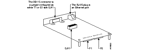
The DB-15 connector on the daughter card is configured as either a T1 or E1 trunk with SW1 as described in the chapter "Installing Cisco 3800 Cards." The T1/E1 trunk pinout is illustrated in Figure 4-4 and described in Table 4-5.

| Pin | Signal Definition | |
|---|---|---|
1 | TxTIP | Transmit TIP |
| 2 | Tx Signal GND | Transmit Signal Ground |
| 3 | RxTIP | Receive TIP |
| 4 | Rx Signal GND | Receive Signal Ground |
| 5 | - | - |
| 6 | - | - |
| 7 | - | - |
| 8 | - | - |
| 9 | Tx RING | Transmit Ring |
| 10 | - | - |
| 11 | Rx RING | Receive Ring |
| 12 | - | - |
| 13 | - | - |
| 14 | - | - |
| 15 | - | - |
The RJ-45 port on the daughter card provides support for a 10BaseT Ethernet connection. The pinout of the port is described in Table 4-6.
| Pin | Signal | Direction |
|---|---|---|
| 1 | Tx+ | Out |
| 2 | Tx- | Out |
| 3 | Rx+ | In |
| 4 | - | - |
| 5 | - | - |
| 6 | Rx- | In |
| 7 | - | - |
| 8 | - | - |
|
|